
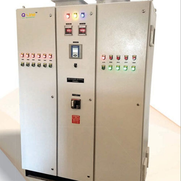
A 250 kVAR APFC (Automatic Power Factor Correction) Panel is designed to provide up to 250 kVAR of reactive power compensation to improve the power factor of an electrical installation. Typical Technical Specification Capacity: 250 kVAR System Voltage: 415 V AC, 3 Phase, 50 Hz Power Factor: Maintains 0.98–0.99 automatically Controller: 8-step or 12-step APFC relay Capacitors: Heavy-duty, self-healing metallized polypropylene capacitors Switching: Capacitor-duty contactors or thyristor switches (for fast switching) Protection: MCCB/Incomer HRC fuses or MCBs for each capacitor bank Overvoltage/undervoltage protection Overtemperature protection (if provided) Cooling: Natural or forced ventilation Enclosure: Floor-mounted, powder-coated CRCA steel, IP42/IP54 (as required) Example Step Configuration (250 kVAR) One common arrangement is: Step Rating (kVAR) 1 10 2 10 3 20 4 20 5 40 6 50 7 50 8 50 Total 250 kVAR Other step combinations are also used depending on the load profile. Approximate Current For a 415 V, 3-phase system: I= 3 ×415 250×1000 ≈348 A So the incomer is typically selected around 400 A MCCB (exact rating depends on design, ambient temperature, and applicable standards). Typical Applications Industrial plants Commercial complexes Textile mills Cement plants Steel industries Large HVAC installations Water treatment plants A 250 kVAR APFC panel is generally suitable for facilities with a connected load of roughly 400–600 kW, depending on the existing power factor and the amount of reactive power compensation required. If you need help with design, single-line diagram (SLD), GA drawing, or BOM for a 250 kVAR APFC panel, I can provide those as well.


This is your website preview.
Currently it only shows your basic business info. Start adding relevant business details such as description, images and products or services to gain your customers attention by using Boost 360 android app / iOS App / web portal.
A 250 kVAR APFC (Automatic Power Factor Correction) Panel is designed to provide up to 250 kVAR of r...
2026-07-31T09:23:27
A 250 kVAR APFC (Automatic Power Factor Correction) Panel is designed to provide up to 250 kVAR of reactive power compensation to improve the power factor of an electrical installation. Typical Technical Specification Capacity: 250 kVAR System Voltage: 415 V AC, 3 Phase, 50 Hz Power Factor: Maintains 0.98–0.99 automatically Controller: 8-step or 12-step APFC relay Capacitors: Heavy-duty, self-healing metallized polypropylene capacitors Switching: Capacitor-duty contactors or thyristor switches (for fast switching) Protection: MCCB/Incomer HRC fuses or MCBs for each capacitor bank Overvoltage/undervoltage protection Overtemperature protection (if provided) Cooling: Natural or forced ventilation Enclosure: Floor-mounted, powder-coated CRCA steel, IP42/IP54 (as required) Example Step Configuration (250 kVAR) One common arrangement is: Step Rating (kVAR) 1 10 2 10 3 20 4 20 5 40 6 50 7 50 8 50 Total 250 kVAR Other step combinations are also used depending on the load profile. Approximate Current For a 415 V, 3-phase system: I= 3 ×415 250×1000 ≈348 A So the incomer is typically selected around 400 A MCCB (exact rating depends on design, ambient temperature, and applicable standards). Typical Applications Industrial plants Commercial complexes Textile mills Cement plants Steel industries Large HVAC installations Water treatment plants A 250 kVAR APFC panel is generally suitable for facilities with a connected load of roughly 400–600 kW, depending on the existing power factor and the amount of reactive power compensation required. If you need help with design, single-line diagram (SLD), GA drawing, or BOM for a 250 kVAR APFC panel, I can provide those as well.
2026-07-31T09:23:27


Submit Your Enquiry