An APFC Panel (Automatic Power Factor Correction Panel) is an electrical control panel used to improve the power factor of an electrical system automatically by switching capacitor banks in and out as needed. Main Purpose Reduce reactive power demand from the utility. Improve power factor (typically to 0.95–0.99). Lower electricity penalties imposed by power utilities. Reduce losses in cables and transformers. Increase the efficiency of the electrical distribution system. Main Components Power Factor Controller (PFC Relay) Monitors the system power factor. Automatically controls capacitor switching. Capacitor Banks Provide reactive power compensation. Available in different kVAR ratings. Contactors or Thyristor Switches Connect/disconnect capacitor banks. Thyristor-based systems provide faster switching. Current Transformer (CT) Measures load current and sends signals to the controller. Circuit Breakers / MCCBs / Fuses Protect the panel and capacitor banks. Reactors (if detuned APFC) Protect capacitors from harmonics. Common in industries with VFDs, UPS systems, and nonlinear loads. Working Principle The CT senses the load current. The controller calculates the power factor. If the power factor falls below the set value, the controller switches ON capacitor steps. When the power factor improves or the load decreases, capacitor steps are switched OFF automatically.

This is your website preview.
Currently it only shows your basic business info. Start adding relevant business details such as description, images and products or services to gain your customers attention by using Boost 360 android app / iOS App / web portal.
An APFC Panel (Automatic Power Factor Correction Panel) is an electrical control panel used to impro
2026-06-17T11:23:03
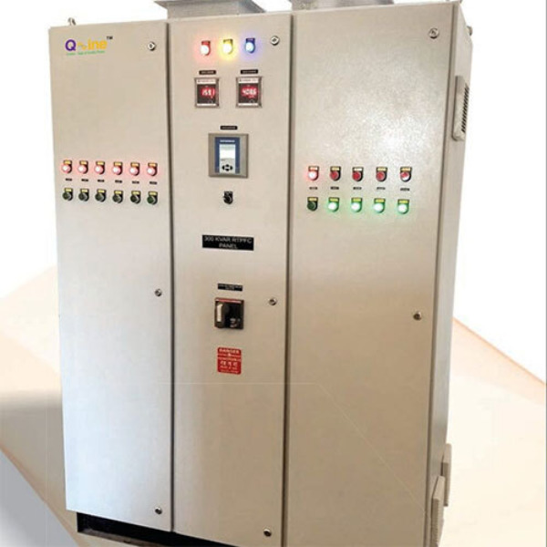
An APFC Panel (Automatic Power Factor Correction Panel) is an electrical control panel used to improve the power factor of an electrical system automatically by switching capacitor banks in and out as needed. Main Purpose Reduce reactive power demand from the utility. Improve power factor (typically to 0.95–0.99). Lower electricity penalties imposed by power utilities. Reduce losses in cables and transformers. Increase the efficiency of the electrical distribution system. Main Components Power Factor Controller (PFC Relay) Monitors the system power factor. Automatically controls capacitor switching. Capacitor Banks Provide reactive power compensation. Available in different kVAR ratings. Contactors or Thyristor Switches Connect/disconnect capacitor banks. Thyristor-based systems provide faster switching. Current Transformer (CT) Measures load current and sends signals to the controller. Circuit Breakers / MCCBs / Fuses Protect the panel and capacitor banks. Reactors (if detuned APFC) Protect capacitors from harmonics. Common in industries with VFDs, UPS systems, and nonlinear loads. Working Principle The CT senses the load current. The controller calculates the power factor. If the power factor falls below the set value, the controller switches ON capacitor steps. When the power factor improves or the load decreases, capacitor steps are switched OFF automatically.
2026-06-17T11:23:03

Submit Your Enquiry